


Audytor H2O
![]()
Programma Audytor H2O ir paredzēta grafiskai palīdzībai aukstā un karstā ūdens sistēmu projektēšanā, tāpat kā tā cirkulācijā gan dzīvojamās, gan sabiedriskās ēkās. Ļauj atlasīt termoregulācijas vārstus cirkulācijas sistēmās.


New features in SET 7.4
In the newest version of program Audytor SET new functions and several enhancements have been implemented to speed up the installation design process.
Main changes:
- Surface systems - a ceiling system and a wall system
- Calculations of resulting cooling efficiency of the installation
| READ MORE |
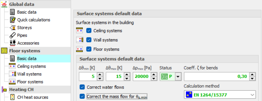
Surface systems
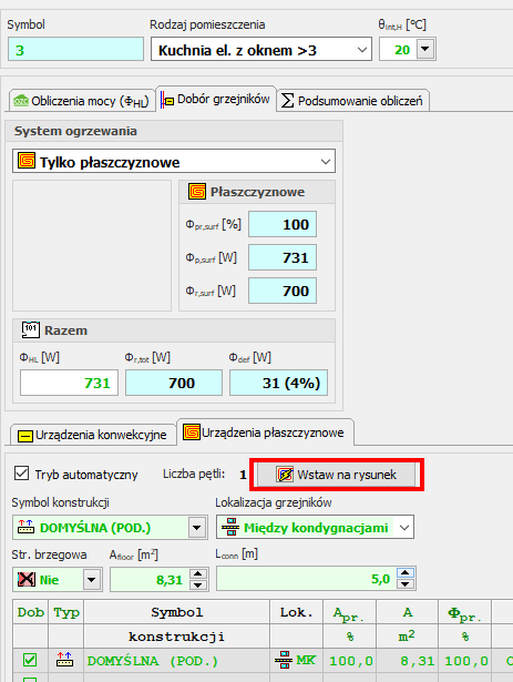
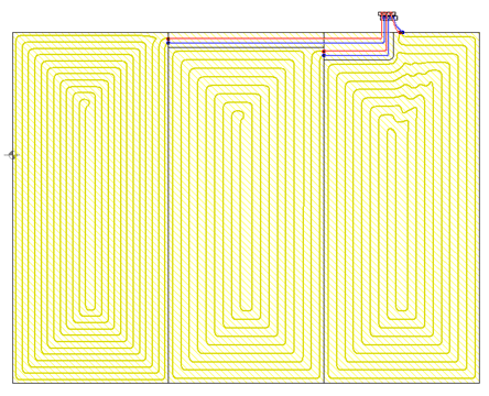
The Audytor SET 7.4 program introduced the possibility of designing surface systems - a ceiling system and a wall system. Among the surface systems, we also will find the well-known floor system
Before starting the design of the surface system, the user should declare the parameters related to the radiator's constrution. The constrution data will be automatically inherited directly into the drawning, significantly reducing the data entry time.
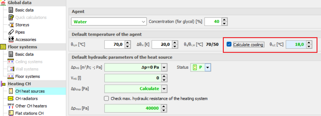
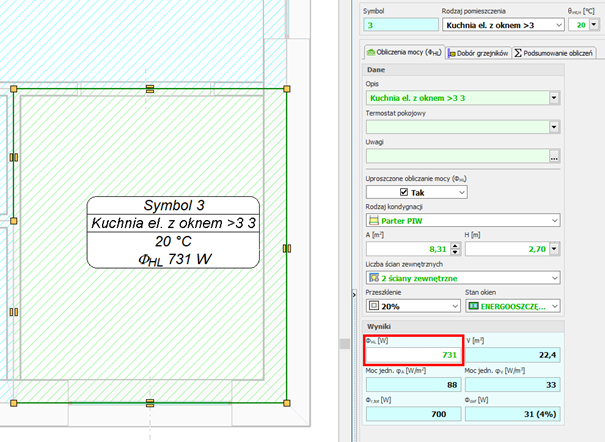
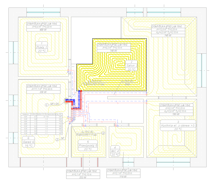
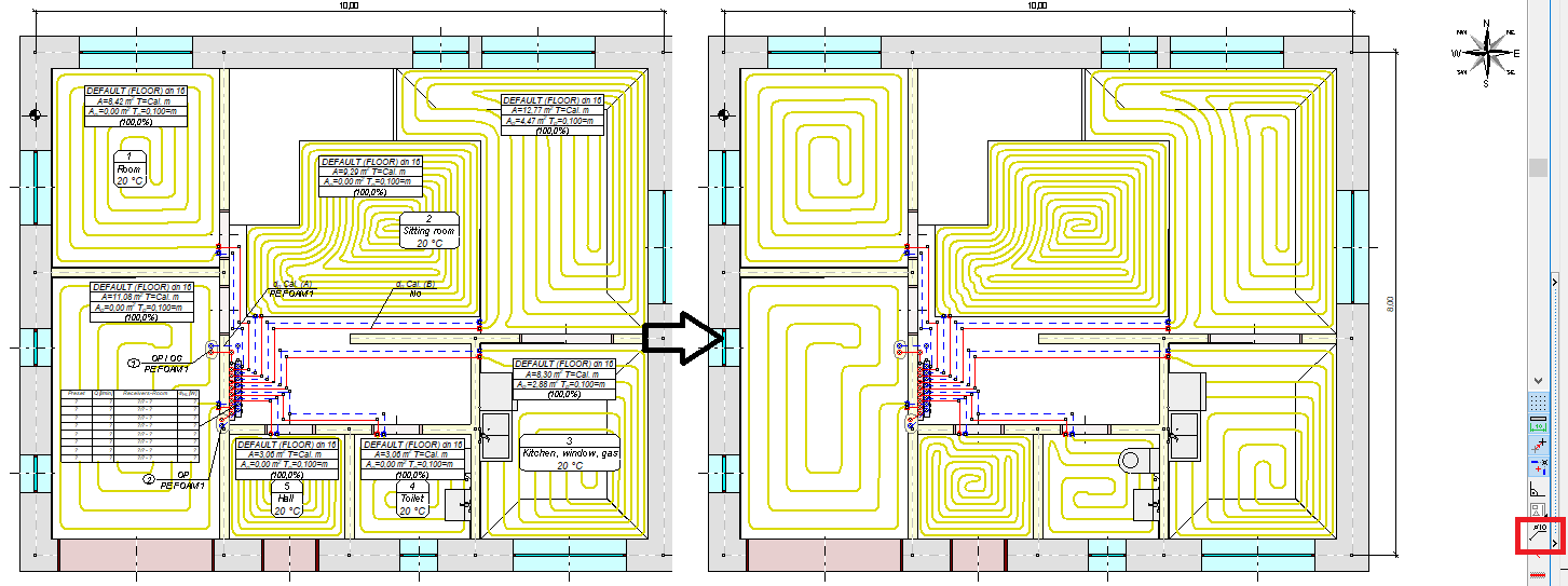
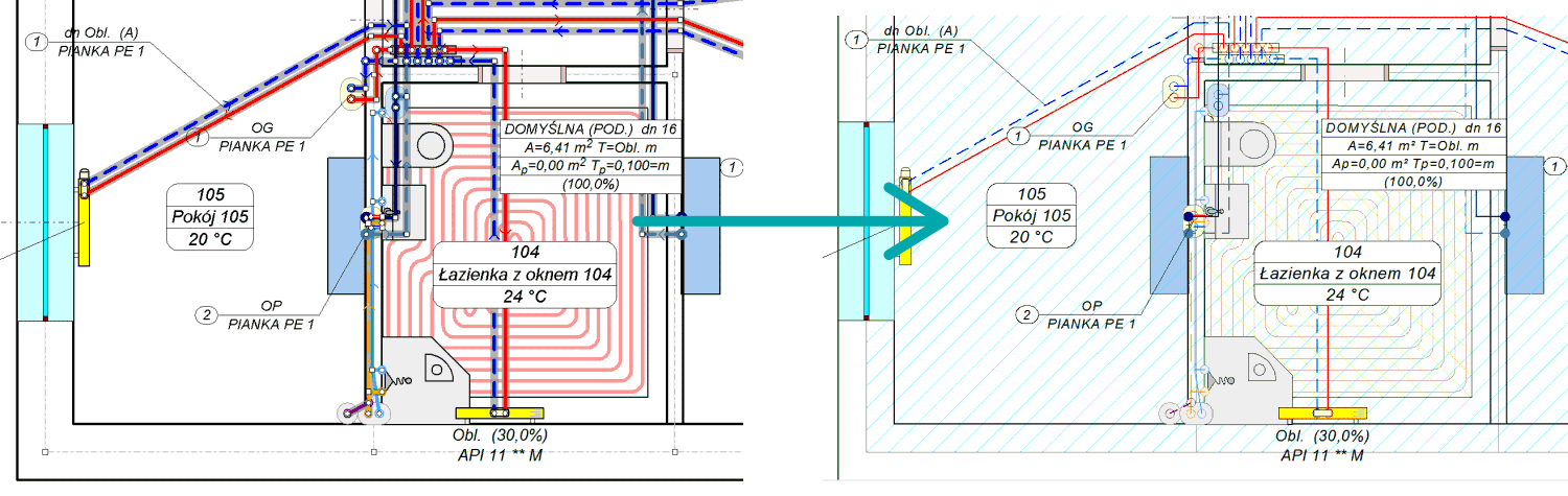
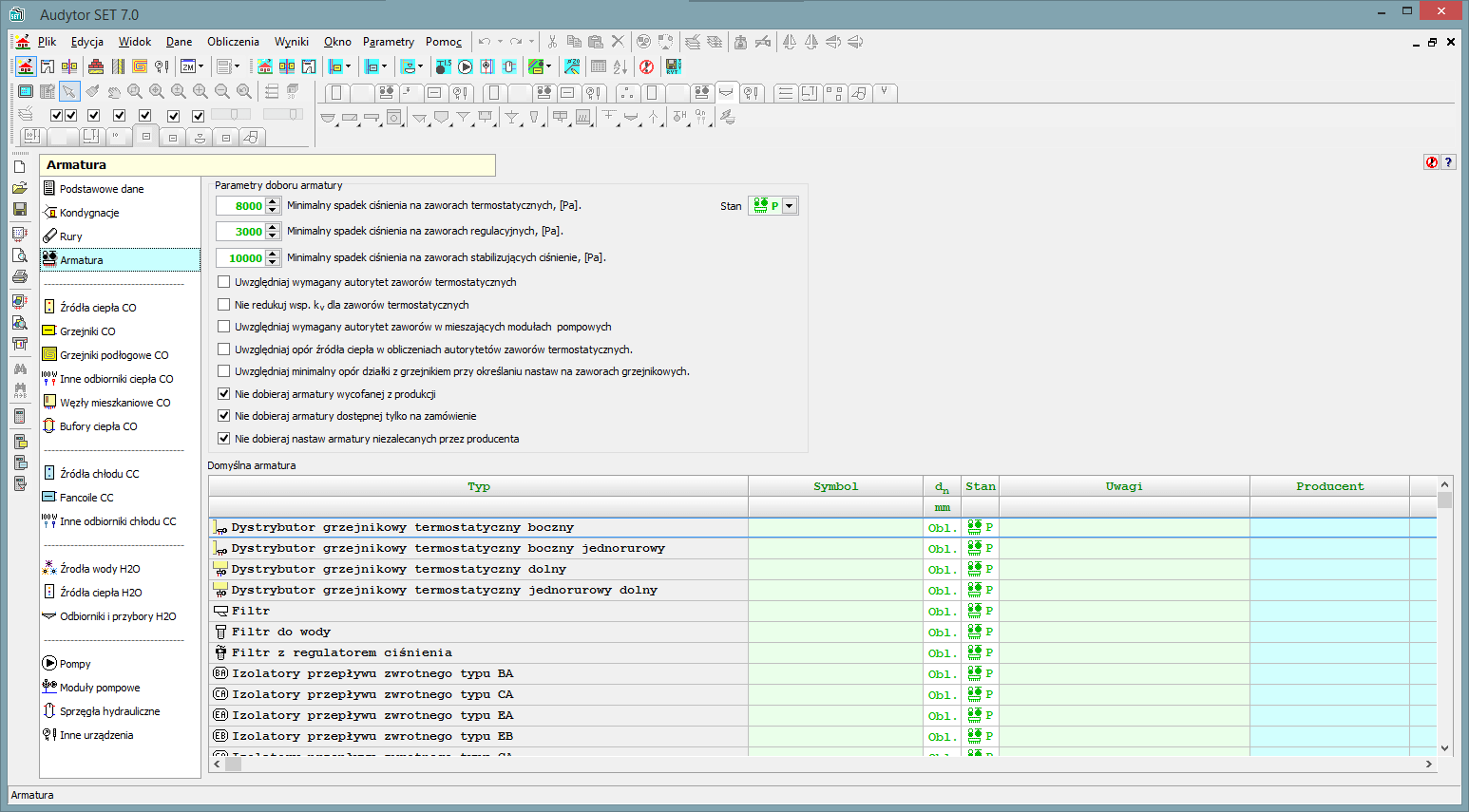
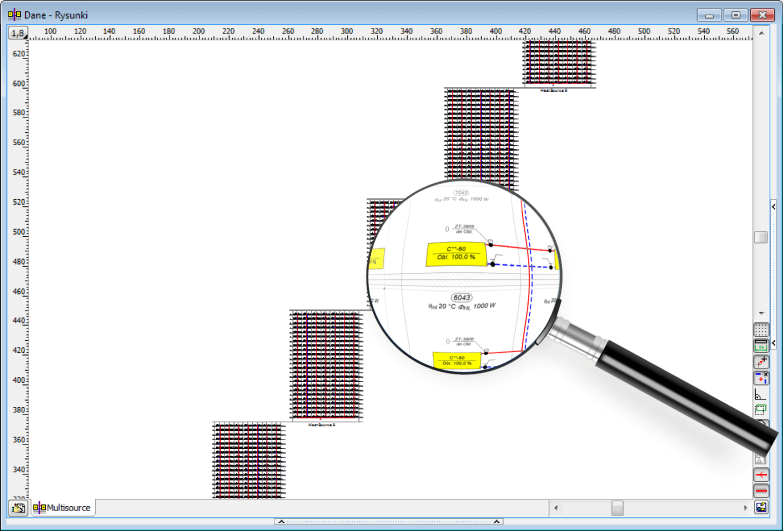
Calculations of the resulting cooling efficiency of the installation
After designing the surface installation with heating parameters, the program will determine the resulting cooling power when switched to cooling mode.
These calculations will be performed if the CC module is activated in the general data and if in CH Heat Sorce Tab the Calculate Cooling option is enabled
The program uses the same flow rate of the agent in cooling mode as in the heating system. After performing the calculations, the results can be read both on the drawing – for example, on a tabular label attached to the manifold – and from the general tabular results.

Calculations of the resulting cooling efficiency of the installation
After designing the surface installation with heating parameters, the program will determine the resulting cooling power when switched to cooling mode.
These calculations will be performed if the CC module is activated in the general data and if in CH Heat Sorce Tab the Calculate Cooling option is enabled.
The program uses the same flow rate of the agent in cooling mode as in the heating system. After performing the calculations, the results can be read both on the drawing – for example, on a tabular label attached to the manifold – and from the general tabular results.
Audytor SET 7.3 - new possibilities!
The latest version of Auditor SET introduced new features and a number of improvements to speed up the installation design process.
The main changes are:
- New concept of work with SET program.
- New Fast Calculation (FC) module, which allows you to perform fast, approximate calculations of the thermal load of rooms and preliminary calculations of installations.
- Improvements in the design process of surface installations.
- Changed layout of the bill of materials.
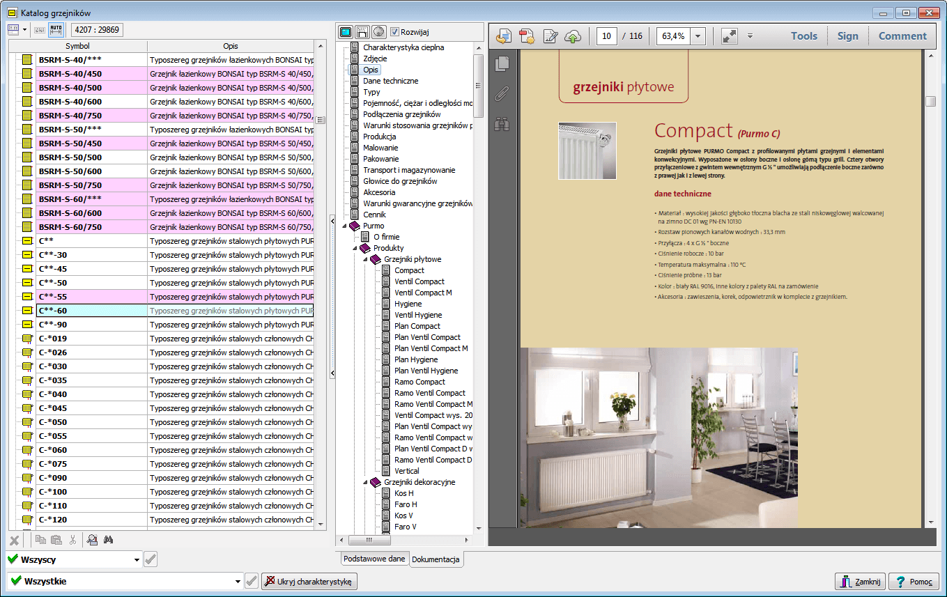
- Changed module for viewing catalog data and selecting devices from catalogs.
- Improvements related to drawing wires.
- Improvements in graphics.
| HOW TO SWITCH TO 7.3 VERSION | GET MORE INFORMATION |
New concept of work with SET program
The new Fast Calculation (FC) module in the SET Auditor provides the opportunity for simplified installation design. It also makes it possible to speed up the creation of professional designs
In professional design mode, elements of simplified design can be used to streamline the design process (fast estimation of heat loss in the absence of results from the OZC program, selection of space heating concepts, etc.).
Both the simplified design and the detailed professional design are saved in the same file, which facilitates further work with the project.
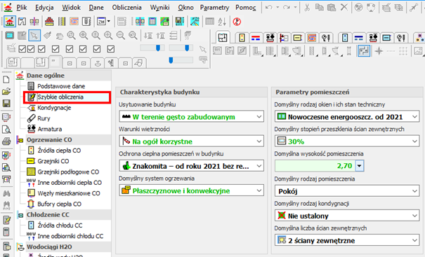
Fast calculations of room thermal load
This function enables calculation of the value of room thermal load in a simplified manner based on a few basic parameters.
Thanks to this function, the designer can select the appropriate method of heating the room and get an idea of the type of heating equipment to be used in the room.
The surface layout suggested by the program can be inserted into the floor plan drawing.
Fast selection of elements without the need to draw the entire installation
When performing fast calculations, the program selects radiator power and duct diameters even if the heat source is not entered. From the default values declared in the general data, it inherits the parameters separately for the installation with radiators, separately for underfloor heating and places a virtual source in the resulting drawing.
Automatic generation of simplified connection routes
After selecting the manifold and individual receivers, the program generates simplified connections automatically.

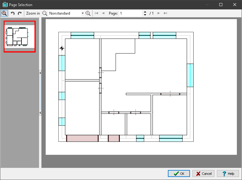
Import of building bases in PDF format
The Audytor program has long been able to import drawings in many popular formats. DWG and DXF formats are particularly suitable for technical drawings. However, in market practice, a large part of the documentation is provided in PDF files. Although it is a general format and not addressed to technical drawings, due to frequent use, the Audytor SET software has the option of importing drawings also in this format.
New graphic design of the Audytor SET program
The graphic design has been changed in the program - both in terms of the graphic style and window organization. Thanks to this, they have become even more transparent
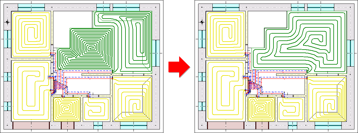
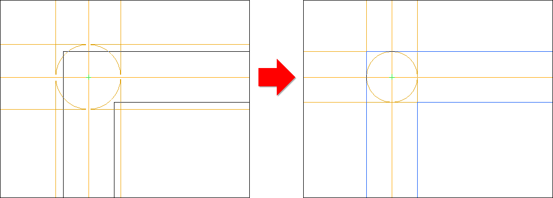
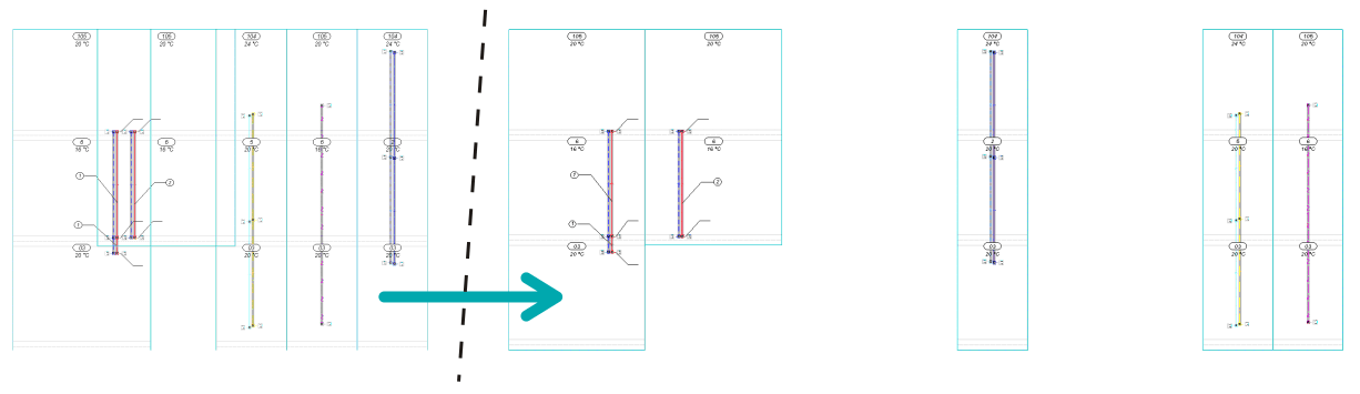
Dividing and joining heating zones, rooms and polygons
Tools for quickly dividing and connecting polygons that define hotplates. One field can be divided into two or three equal fields - horizontally or vertically, respectively. The user can also indicate a dividing line using a broken line. At the same time, the option of combining several cooking zones into one has been introduced.
These functions are especially useful when designing underfloor heating, but can be used for sharing
and joining other polygons (e.g. room zones).

Extending the range of mixing group schemes
Extended range of mixing group schemes with the possibility of local mixing at the manifold.
Drawing in drawing
It is possible to insert a fragment of another drawing in the drawing. This significantly increases the possibility of creating clear technical documentation.
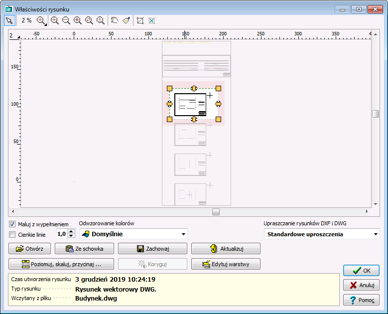
Inserting a fragment of a DWG drawing
The ability to easily use one DWG file containing architectural plans of many floors.
The user can indicate which parts of the DWG file are to be used on each floor and then adjust their position using precision panning tools.
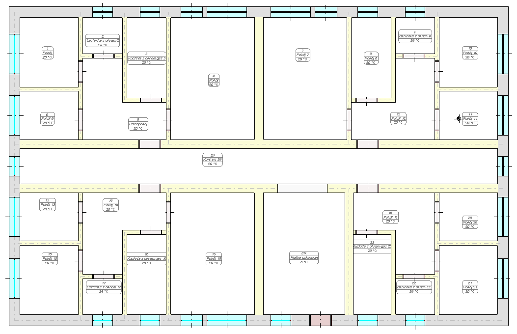
Coloring the walls
Display of walls with filling - gray for external walls and yellow for internal walls. This improves the readability of created drawings.
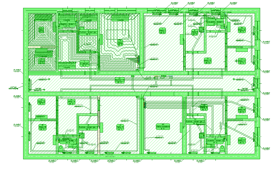
Selection in color
When selecting objects using the window, the selection window is filled with blue, which improves its readability.
Readability of selected objects has also been increased by displaying them with all details in green.
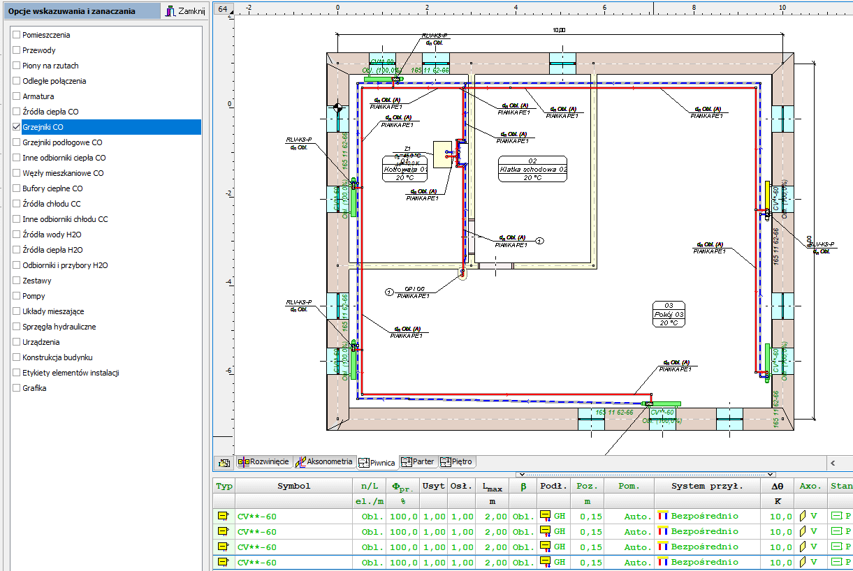
Selective selection
The selective selection function allows you to indicate what elements of the drawings are to be marked (e.g. rooms, pipes, fittings, etc.).
This function is useful when, for example, the user would like to duplicate selected elements from the indicated area to the next floor.
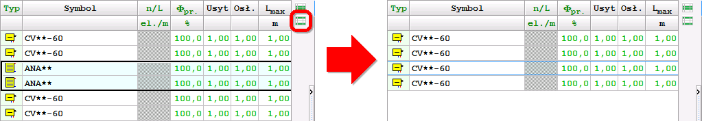
Narrow the range of selected objects in the tables
The functions Leave selected lines and Leave unselected lines allow you to narrow the range of selected objects. After selecting a number of elements in the drawing window, you can then remove from the selection the items indicated in the table or just leave those items.

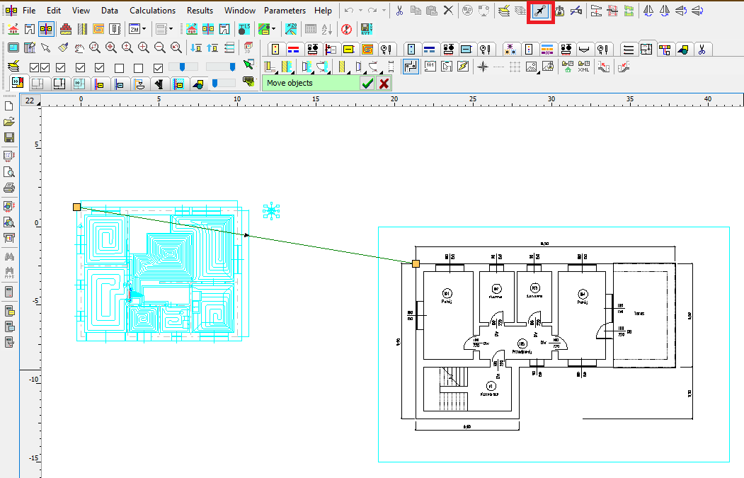
Precise moving of objects
This function enables precise moving of objects. The user defines the displacement vector, i.e. specifies the start and end points.
This function, combined with the Magnifier tool, enables very precise moving of objects. It is very useful, in the case of matching architectural objects on different floors. Just enable the display of the previous floor and then indicate the corresponding points on the architectural plans of two floors.
Improved critical flow display
When you turn on critical flow display, the other elements of the drawings are displayed less intensively. This makes it even easier to orient yourself in the course of critical circulation.
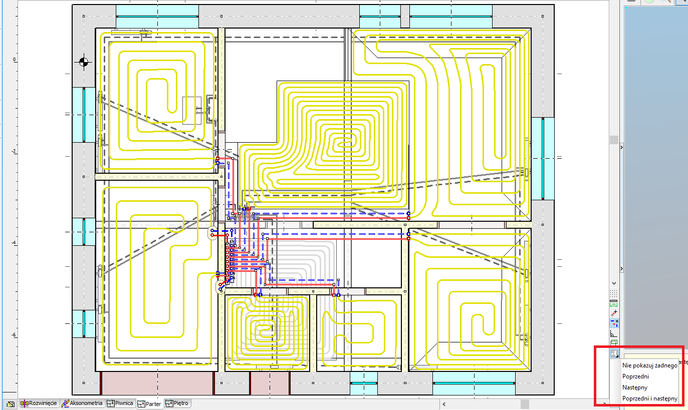
Drawing adjacent floors
Expanding the possibilities of displaying (drawing) the previous floor.
Currently, elements of the previous storey or the next storey can be displayed, or both. This facilitates adjusting architectural projection positions and location of installation risers.
Temporarily turn off of the label display
The option of temporarily turning off the display of labels during design, improves the readability of drawings on the screen in situations where labels are not necessary.
Adjusting wall thickness
This option allows you to change the thickness of the walls when drawing them:
– CTRL + left square bracket - reducing the wall thickness,
– CTRL + right square bracket - increasing wall thickness.
The same effect can be achieved by pressing the CTRL key while holding the mouse wheel. This function allows easy adjustment of the wall thickness to the loaded building foundation (planview).
Export extension to Excel
The ability to export to Microsoft Excel not only individual tables, but also all tables and diagnostics at once. This significantly reduces exporting time if you need to save a number of tables.
Import and export of drawings in DWG format
The program has been equipped with the latest cooperation module with DWG and DXF files.
It allows among others:
- Loading DXF and DWG drawings in the newest versions.
- UNICODE text support for most characters to be displayed correctly.
- Export of drawings in the following formats: DWG, DXF, PDF, SVG, CGM, HPHL, SWF.
- Significantly faster display of complex drawings thanks to the simplified paint function.
- A more realistic export of drawings to DXF and DWG files.
- Saving raster drawings in DXF and DWG files.
- More convenient management of drawing layers

Import of building bases from Autodesk® Revit®
The function allows to create layout of corresponding to the levels on which rooms have been defined in Autodesk® Revit®. The transfer of data takes place via a file generated in Autodesk® Revit® using the Audytor gbXML plugin.

Export of the installation project to Autodesk® Revit®
The function allows you to export the installation project to a file that can later be loaded into Autodesk® Revit® using the Audytor SET plugin for Revit.
The function allows you to export from the data and export from the results. Export from data allows you to save even an incomplete installation project (not recalculating), for example, the arrangement of the water risers, or the layout of the radiators. Export from results allows us to use technical data of selected pipes and devices in Autodesk® Revit®, eg pipe diameters, valve settings, radiator sizes, and pipe spacing in underfloor heating. In addition, physical quantities are available, such as the medium speed, the power of the radiator, and pressure losses.

| 7.2 Pro | 7.2 Basic | 7.1 Pro | 7.1 Basic | 7.0 Pro | 7.0 Basic | 365 Pro | 365 Basic | 1.5 | |
|---|---|---|---|---|---|---|---|---|---|
| Calculations of the resulting cooling efficiency of the installation |

|
|
|||||||
| Calculations of the resulting cooling efficiency of the installation |
|
|
|||||||
| New concept of work with SET program |
|
|
|||||||
| Fast calculations of room thermal load |
|
|
|||||||
| Fast selection of elements without the need to draw the entire installation |
|
|
|||||||
| Automatic generation of simplified connection routes |
|
|
|||||||
| Import of building bases in PDF format |
|
|
|
|
|||||
| New graphic design of the Audytor SET program |
|
|
|
|
|||||
| Dividing and joining heating zones, rooms and polygons |
|
|
|
|
|||||
| Extending the range of mixing group schemes |
|
|
|
|
|||||
| Drawing in drawing |
|
|
|
|
|||||
| Inserting a fragment of a DWG drawing |
|
|
|
|
|||||
| Coloring the walls |
|
|
|
|
|||||
| Selection in color |
|
|
|
|
|||||
| Selective selection |
|
|
|
|
|||||
| Narrow the range of selected objects in the tables |
|
|
|
|
|||||
| Precise moving of objects |
|
|
|
|
|||||
| Improved critical flow display |
|
|
|
|
|||||
| Drawing adjacent floors |
|
|
|
|
|||||
| Temporarily turn off of the label display |
|
|
|
|
|||||
| Adjusting wall thickness |
|
|
|
|
|||||
| Export extension to Excel |
|
|
|
|
|||||
| Display of system pipes with actual diameters |
|
|
|
|
|
|
|||
| Intelligent duplication of system components - "down". |
|
|
|
|
|
|
|||
| A system of editable keyboard shortcuts |
|
|
|
|
|
|
|||
| The function of organizing labels on several floors at the same time |
|
|
|
|
|
|
|||
| Import and export of drawings in DWG format |
|
|
|
|
|
|
|||
| Import of building bases from Autodesk® Revit® |
|
|
|
|
|||||
| Export of the installation project to Autodesk® Revit® |
|
|
|
|
|||||
| The ability to check the correctness of the floors layout |
|
|
|
|
|
|
|
|
|
| Creating a list of fittings |
|
|
|
|
|
|
|
|
|
| Desiging on plan views |
|
|
|
|
|
|
|
|
|
| Desiging on diagrams |
|
|
|
|
|
|
|
|
|
| Loading of building bases with the results of heat load from the Audytor HL program |
|
|
|
|
|
|
|
|
|
| Loading the list of rooms with the results of the heat load from the Audytor HL software |
|
|
|
|
|
|
|
|
|
| The ability to draw building bases (walls, windows and doors) |
|
|
|
|
|
|
|
|
|
| Automatic creation of diagrams of risers based on plan views |
|
|
|
|
|
|
|
|
|
| Determining the design water flows in the pipes |
|
|
|
|
|
|
|
|
|
| Selection of pipe diameters |
|
|
|
|
|
|
|
|
|
| Determining the hydraulic resistance of individual elements of the installation |
|
|
|
|
|
|
|
|
|
| Determining the required available pressure |
|
|
|
|
|
|
|
|
|
| Regulation of water flows in the DHW circulation network by selecting appropriate control elements (valves with pre-settings, orifices, thermostatic valves) |
|
|
|
|
|
|
|
|
|
| Calculation of the required water flow in the DHW circulation network by the thermal method consisting in determining the cooling of hot water in individual areas |
|
|
|
|
|
|
|
|
|
| Selection of thermal insulation for pipes |
|
|
|
|
|
|
|
|
|
| Selection of temperature settings of thermostatic valves, taking into account the water cooling in the circulation pipes |
|
|
|
|
|
|
|
|
|
| Auxiliary lines indicating characteristic points |
|
|
|
|
|
|
|
|
|
| Drawing lines in pairs (CW - HW) |
|
|
|
|
|
|
|
|
|
| Drawing lines with a continuous broken line |
|
|
|
|
|
|
|
|
|
| Automatic connection of receivers to distribution pipes |
|
|
|
|
|
|
|
|
|
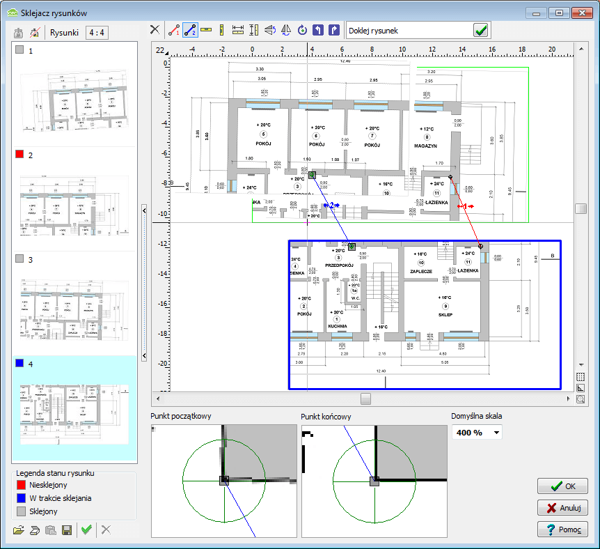
| Bonding and scaling drawings |
|
|
|
|
|
|
|
|
|
| Grafiskais redaktors |
|
|
|
|
|
|
|
|
|
| Duplicating fragments of drawings within a storey and to the next storeys |
|
|
|
|
|
|
|
|
|
| Noklusējuma datu pārmantošana |
|
|
|
|
|
|
|
|
|
| Creating mirror images of parts of drawings |
|
|
|
|
|
|
|
|
|
| Working in a shared environment Audytor SET |
|
|
|
|
|
|
|
|
|
| Backup system of data files |
|
|
|
|
|
|
|||
| Extensive directory database |
|
|
|
|
|
|
|
|
|
| "Find and Replace" function in tables |
|
|
|
|
|
|
|
|
|
| Data diagnostic system |
|
|
|
|
|
|
|
|
|
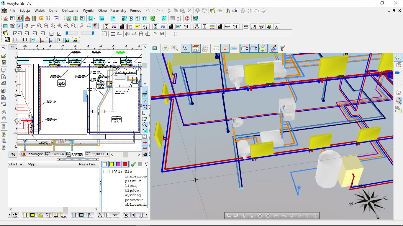
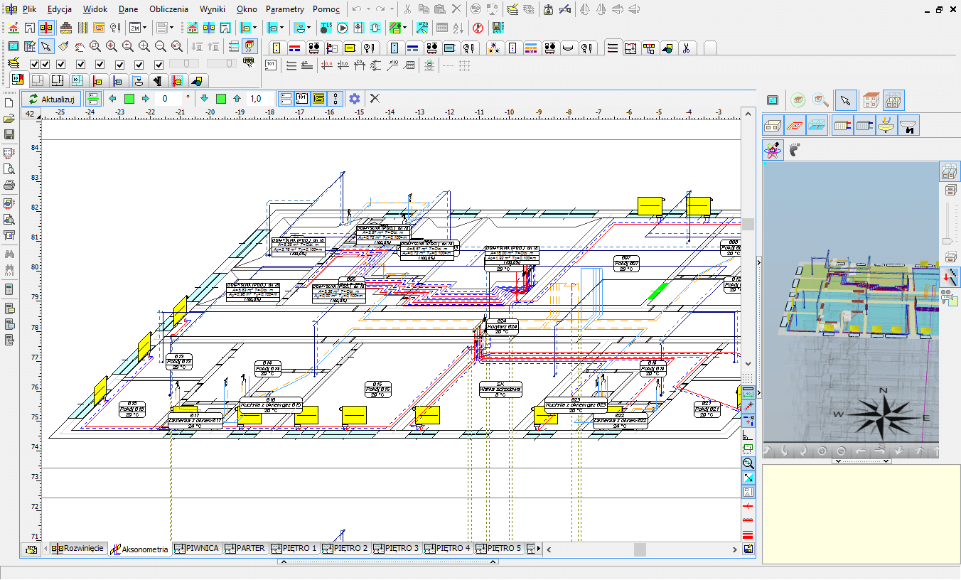
| Three-dimensional visualization of the installation |
|
|
|
|
|
|
|
|
|
| Extended error diagnostics |
|
|
|
|
|
|
|
|
|
| Automatic axonometry of the installation |
|
|
|
|
|
|
|||
| The function of organizing zones of risers on the diagrams |
|
|
|
|
|
|
New program features
- Possibility to import building bases from Autodesk® Revit® via a gbXML file,
- Possibility to export data about the designed installation to Autodesk® Revit®..
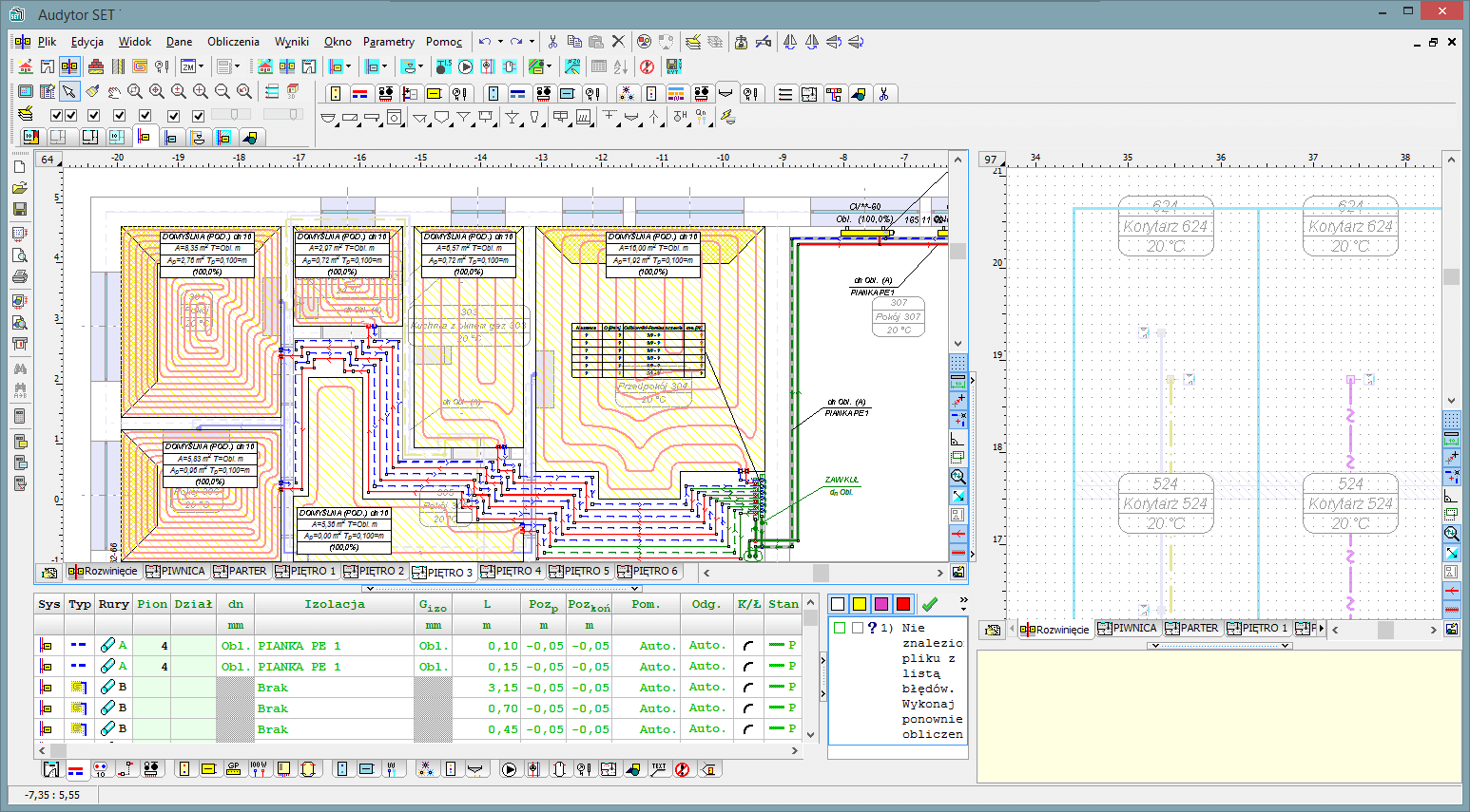
Graphic editor
A drawing with marked room zones is necessary to create a project. They can be drawn manually in the program or loaded together with bases from the HL program. If a three-dimensional model of a building has been created in the HL program, the drawings with the results will be loaded into the program. The building entered in tabular form will be loaded as a list of rooms with the results.
The most comfortable mode of operation allows you to take full advantage of the possibilities of cooperation with the HL program:
- Uploading building bases to the HL program from files such as DWG, DXF, WMF, JPG.
- Drawing a building model in the HL program and making thermal calculations.
- Loading the results from the HL program in the system design program (heat load values and floor plans)
- Drawing the installation and making calculations.
Designing an installation can be carried out only on a diagram, only on plan views, or partially on plan views and partially on a diagrams. It is also possible to combine fragments of installations drawn on plan views with elements drawn on diagrams.
In the case of drawing onplan views, the program automatically creates a simple diagram of risers, "fastening" individual projections. The program Audytor SET has been equipped with a three-dimensional visualization module of the installation, analogous to the building visualization module, available in the Audytor HL program.
Default data inheritance system
A significant part of the parameters introduced at the beginning of defining the building are typical data for the entire building (the so-called default data). When entering general data, the user can define for each device default catalog symbol. This symbol is automatically assigned to each device in the drawing. The previously defined default catalog symbol can be changed at any time, also after inserting the device into the drawing. Changing the symbol of a device in the general data will change the symbols of all devices of a given type, unless the symbol has been “firmly” entered for a given device.
The data is edited in the table, which allows you to specify parameters for many drawing elements simultaneously. Linking the drawing to the table makes the element edited in the table highlighted in the diagram.
The data inheritance system allows you to:
- significant time savings at the data entry stage (without the need to repeatedly enter repeated data),
- very quick change of data in case of a change in design assumptions or creating variant projects.
New program features Audytor
- Import and export of drawings in DWG format
- The function of organizing the zones of risers in the development
- Data file backup system
- A mechanism that automatically generates an axonometric scheme of the designed installation
- Ability to display installation pipes with actual diameters
- Mechanism of intelligent duplication of installation elements
- The function of arranging labels on several storeys at the same time (in plan views and axonometry drawings) and a mechanism for duplicating labels on adjacent storeys
- Improving the drawing of sewage installations.
- A system of keyboard shortcuts to assign simple button combinations to the most used drawing tools.
- Improvements in editing drawing layer properties.
- Improvements in displaying information about the circulation by a given heater / receiver.
Programma ļauj veikt pilnu hidraulisko aprēķinu sistēmai
- aprēķināt ūdens plūsmu caurulēs;
- atlasīt cauruļu diametru;
- aprēķināt atsevišķu sistēmas sastāvdaļu hidraulisko pretestību kopā ar nepieciešamo pieejamo spiedienu;
- atlasīt spiediena regulatorus;
- veikt ūdens plūsmas kontroli ēkas karstā ūdens cirkulācijas sistēmā, atlasot piemērotas regulācijas sastāvdaļas (sākotnējos regulācijas vārstus, uzgaļus, termoregulācijas vārstus);
- kalkulēt nepieciešamās ūdens plūsmas ēkas karstā ūdens cirkulācijas sistēmā ar termisko metodi;
- atlasīt trīsceļu jaucējvārstus dzīvojamās ēkas karstā ūdens sistēmā;
- atlasīt cauruļu siltumizolāciju.
Ieguvumi no programmas
-
Iespēja projektēt vairākas sistēmas vienā projektā.
-
Neierobežots instalācijas izmērs (pat tūkstošiem piederumu un pieslēgumu vietu).
-
Ātrs aprēķinu veikšanas process.
-
Ēkas izklājums izplatītākajos vektoru un rastra formātos.
Aprēķinu laikā tiek veikta pilna datu pareizības pārbaude, tostarp:
- attēla;
- atsevišķu datu diapazona (skaitļi - telpu simboli, caurules, kataloga simboli utt.);
- cauruļu savienojumu saskaņotība sistēmas ietvaros (nesavienotas caurules, nepareizi savienotas caurules utt.);
- piederumu atrašanās vieta.
Aprēķinu rezultātu pareizības pārbaude, tostarp:
-
aģenta plūsmas ātrums caurulēs;
-
ūdens spiediens pirms saņēmējiem;
-
nepietiekams spiediens ķēdē ko rada galveno piederumu trūkums vai to nepietiekamība cirkulācijas ķēdē;
-
cauruļu izolācija;
-
ūdens dzesēšana caurulēs.
Datu un aprēķinu pareizības pārbaudes rezultātā tiek izveidots konstatēto kļūdu saraksts, kurā uzskaitīts kļūdu tips un atrašanās vieta.
Programma ir aprīkota ar ātru kļūdu atrašanās vietas noteikšanas mehānismu (automātiska tabulas atrašanās vieta, rinda un kolonna ar kļūdainajiem datiem kopā ar norādi uz kļūdaino vienumu instalācijas diagrammā).
Aprēķinu rezultāti tiek parādīti gan grafiskā, gan tabulas formātā. Attēla slāņu formātu un iezīmju formātu atsevišķiem sistēmas komponentiem var brīvi modificēt (iezīmēto daudzumu, krāsu, burtu lielumu utt. izvēle). Aprēķinu rezultātus var attēlot arī sistēmas plāna skatā.
Visu tabulu saturu var formatēt (izvēle ar kolonnām un rindām, ko rādīt, burtu lielums) un kārtot atbilstoši brīvi izvēlētam filtram.
Tabulas ar aprēķinu rezultātiem var izdrukāt un pārvietot uz citām aplikācijām, kas darbojas Windows vidē (piem. izklājlapa, tekstapstrādes programma utt.). Drukas priekšskatījuma funkcija ļauj skatīt lapas pirms izdrukāšanas.
Aprēķinu rezultātus un instalācijas diagrammas var arī attēlot grafiski plāna skatos un nosūtīt uz ploteri vai printeri. Lietotājs var izvēlēties grafiskās attēlošanas mērogu. Grafiskas attēlošanas priekšskatījuma funkcija ļauj pārbaudīt attēlus pirms grafiskas attēlošanas. Lielākus attēlus var drukāt vai attēlot grafiski fragmentos, kurus pēc tam var savietot vienā izdrukā, līdz ar to ar parastu A4 printeri var iegūt pat liela izmēra attēlus.
Datu ievade
Programmā datus var ievadīt grafiski plāna skatā vai diagrammās. Nepieciešamā informācija par rasētajiem elementiem ir iekļauta kopā ar plāna skatiem vai diagrammām izveidotajās tabulās. Veidojot tabulu, ir iespējams ātri izlabot ar atsevišķām caurulēm, radiatoriem, stiprinājumiem, kā arī ar visām atlasītajām elementu grupām saistītos datus. Katrs sistēmas komponents ir aprīkots ar apstiprinājuma un atbalsta sistēmu, ar kuru var saņemt informāciju par ievietoto daudzumu vai attiecīgos kataloga datus.
Lai datu ievade būtu vienkāršāka, programmatūra ietver turpmāk minētās iespējas.
-
Iespēju vienlaikus labot daudzus sistēmas komponentus.
-
Iespēju izmantot jau gatavus blokus.
-
Viedas funkcijas, kas veic jebkuru rasējuma detaļu dublēšanu horizontāli un vertikāli kopā ar atbilstošu elementu pārnumurēšanu.
-
Iespēju noteikt neierobežotu pielāgoto bloku skaitu, ko veido jebkuras rasējuma daļas.
-
Ātru piekļuvi papildu informācijai par ievietotajiem daudzumiem.
-
Iznirstošas pogas, lai būtu vieglāk piekļūt biežāk izmantotajiem komponentiem.
-
Funkciju, kas dinamiski sasaista datus no rasējuma ar datiem tabulā.
-
Funkcijas, kuras automātiski savieno stiprinājumus, radiatorus un citus sistēmu komponentus ar caurulēm.
-
Automātisku stāvvadu izveidi uz plāna skatu bāzes.
-
Datu labošanu tabulas veidā, piedāvājot iespēju iestatīt vairāku atlasītu elementu parametrus vienlaikus.
-
Dinamisku sasaisti starp rasējuma datiem tabulā, kas izgaismojas rasējumā, ja elements tiek labots tabulā.
Datu diagnostikas sistēma
Katrs ievietotais komponents ir aprīkots ar apstiprinājuma un atbalsta sistēmu, ar kuru var iegūt informāciju par vērtībām vai kas atsauc atbilstošo katalogu, kā arī ar datu testu.
Ēkas izklājumi
Programma ļauj izveidot pilnu grafisko dokumentāciju sistēmas projektēšanai, pateicoties iespējai parādīt aprēķinu rezultātus stāvu plāna skatos. Bieži ir jāpievieno veidojamā projekta attēli. Attēlus var ievadīt, nolasot attēlus no faila, skenējot vai ielīmējot tos no starpliktuves. Pēc ievadīšanas attēliem bieži ir nepieciešama izlīdzināšana, kalibrēšana, apgriešana un citas korekcijas.
Tehniskie rasējumi (piem. izklājumi) tagad parasti tiek veidoti ar datoru. Līdz ar to tie ir pieejami elektroniskā formātā kā faili. Vektoru formāti (piem. DWG, DXF, WMF, EMF) ir vispiemērotākie tehniskiem rasējumiem. Attēlu failus var veidot skenējot, tad tie gandrīz vienmēr ir pieejami rastera formātā (BMP, JPG, JPEG, TIF, TIFF, GIF, ICO, PNG).
Parasti attēla ielādēšanas laikā būs jāaizpilda informācija dialoga logā "Attēla vienības". Pēc tam, kad attēls ir ievietots programmā, parasti ir jāveic tā izlīdzināšana un apgriešana, var būt nepieciešama arī kalibrēšana, lai pielāgotu attēlu tā elektroniskajam ekvivalentam. Ir iespējams izvēlēties skenējamā attēla izšķirtspēju un kvalitāti un saglabāt skenētos dokumentus izvēlētajā grafiskajā formātā. Programma ir aprīkota ar skeneriem, kas savietojami ar TWAIN specifikāciju.
Bonding and scaling drawings
HL programs and CH are equipped with the function of Graphic creation of a building model. This function gives you the opportunity to draw a building model. To simplify the action of drawing, you can load a drawing base into the program. The file being loaded can come from an external program for creating technical drawings (eg DWG), or from a scanned drawing (eg JPG). The scanned drawing can be divided into several files. Drawings scanned into several files usually do not keep the scale precisely enough. They can also be rotated relative to each other by a small number of degrees.
Drawing bonding allows you to quickly scale multiple scanned drawings (in different sizes and rotated) and bond them with one another.
Grafiskais redaktors
Lai izveidotu sistēmas projektu, ir jāveic rasēšana ar atzīmētām telpas zonām. Projektētājs var rasēt telpas zonas manuāli vai ielādēt tās kopā ar plāna skatiem no siltumslodzes programmas (OZC 6.5). Ja OZC 6.5 programmā ir izveidots trīsdimensionāls ēkas modelis, CH programmā tiks importēti plāna skati kopā ar siltumslodzes rezultātiem. Tabulas veidā ievadītā ēka tiks ielādēta kā telpu saraksts ar rezultātiem.
Turpmāk aprakstīts ērtākais darba veids, izmantojot pilnu sadarbības potenciālu starp programmām OZC 6.5 un CH 4.0.
-
Ēkas plāna skatu ielāde no tādām datnēm kā DWG, DXF, WMF u. tml. OZC 6.5 programmā.
-
Ēkas 3D modeļa rasēšana OZC 6.5 programmā un termisko aprēķinu izpilde.
-
Rezultātu ielāde no OZC 6.5 programmas CH 4.0 programmā (siltumslodze un plāna skati).
-
Sistēmas rasēšana programmatūras instalācijas OZC 6.5 programmā un aprēķinu veikšana.
Sistēmas projektu var izveidot diagrammas veidā, plāna skatā un daļēji diagrammas un daļēji plāna skatā.
Ja sistēmas rasējums tiek veidots plāna skatā, programma automātiski izveido diagrammu, kas „savieno“ plāna skatus.
Noklusējuma datu pārmantošana
Liela daļa ēkas definēšanas sākumā ievadīto datu ir visai ēkai raksturīgie dati (tas ir, noklusējuma dati). Šos datus izmanto datu pārmantošanas sistēma.
Papildus citiem datiem lietotājs var noteikt katrai ierīces klasei arī noklusējuma kataloga simbolu. Simbols tiek automātiski piešķirts (pārmantots) katrai ierīcei, kas ievietota projektā. Noklusējuma kataloga simbolu var jebkurā brīdī izmainīt pat pēc ierīču ievietošanas rasējumā. Izmainot simbolu kopējos datos, tiks izmainīti visu šī veida ierīču simboli, ja vien dotajam elementam nav atsevišķi ievadīts cits simbols. Tādā pašā veidā iespējams pārmantot daudzus citus parametrus.
Dati tabulās tiek laboti, ar ko iespējams veikt vairāku elementu noteikšanu vienlaikus. Sasaiste starp rasējumu un tabulu izgaismojas rasējumā, ja elements tiek labots tabulā.
Ar datu pārmantošanas sistēmu ir iespējams:
-
būtiski ietaupīt laiku uz datu ievades rēķina (novērš vajadzību ievadīt atkārtotus datus vairākas reizes);
-
ātri mainīt atkārtotus datus, ja mainās projekta pieņēmumi vai tiek sagatavoti projekta varianti.
Working in a shared environment Audytor SET
The program (since version 7.0) has been created as a module of the Audytor SET program and enables the simultaneous design of cooling, cold and hot water systems together with circulation and central heating installations. Individual modules of the program cooperate with each other and use a common 2D and 3D graphic environment.
Backup system of data files
The program has a mechanism that automatically creates a set of project backups (up to 8 files).
Data files are backed up every time data is saved, with the new files overwriting the older files so that at least one copy of the file from each stage of the project work is always kept.
This function will allow you to recover the project file even if its last versions are overwritten or damaged.
Extensive directory database
The program catalog database contains information on pipes, fittings and radiators. This database is constantly developed.
In one design, fittings, pipes and radiators from different companies can be used simultaneously.
Rasēšanas atbalsta funkcijas
-
Peles kursors ieņem neliela attēla formu, kas atbilst pašreiz izmantotajai funkcijai.
-
Tiek rādītas papildu rindas, iesakot automātisku konkrētu punktu savienojuma izveidi (piemēram, radiatoru savienojuma vietas).
-
Caurules ir iespējams uzzīmēt kā pārus (padeve/atplūde) ar atlasītām atstarpēm, kuras, ja nepieciešams, automātiski pielāgojas pievienotajām ierīcēm (piemēram, radiatoru savienojuma punktu atstarpēm).
-
Rasējot caurules kā daudzstūru ķēdi, tiek samazināts nepieciešamo peles klikšķu skaits.
-
Automātiska radiatoru ievietošana zem logiem.
-
Automātiska radiatoru savienošana ar apakšējo cauruļu savienojumu.
-
Jebkuru rasējuma daļu dublēšanas iespēja viena stāva ietvaros vai uz nākamo stāvu.
-
Iespēja izveidot elementu spoguļattēlu.
-
Iespēja izmantot jau gatavus blokus. Izmantojot kopā ar programmatūru pieejamo tādu rasējumu (bloku) standarta detaļu kā stāvvadu stāvi, dzīvokļa elementi vai kolektoru sistēmu daļas bibliotēku, ir iespējams ātri izveidot diagrammu.
-
Iespēja noteikt neierobežotu pielāgoto bloku skaitu, ko veido jebkuras rasējuma daļas. Iepriekš izveidotos blokus var izmantot turpmākajos projektos.

Three-dimensional visualization of the installation
The function allows you to export the installation project to a file that can later be loaded into Autodesk® Revit® using the Audytor SET plugin for Revit.
The function allows you to export from the data and export from the results. Export from data allows you to save even an incomplete installation project (not recalculating), for example, the arrangement of the water risers, or the layout of the radiators. Export from results allows us to use technical data of selected pipes and devices in Autodesk® Revit®, eg pipe diameters, valve settings, radiator sizes, and pipe spacing in underfloor heating. In addition, physical quantities are available, such as the medium speed, the power of the radiator, and pressure losses.

Automatic axonometry of the installation
The program since version 7.1 has a mechanism that automatically generates the axonometric scheme of the designed installation.
Axonometry drawing can be printed or exported to DWG format, which allows to create a complete project documentation.
The axonometry schema also allows displaying the scheme of the entire installation in one drawing allowing for a more precise orientation in the project and selecting and simultaneously editing the element data on different floors, which significantly speeds up the procedure of design modification and installation adjustment.
The function of organizing zones of risers on the diagrams
In the drawing of the automatically created installation diagrams, the Organize button that has been added, enables the intelligent positioning of the zones of risers based on the data from the storey's plan views.
The program maintains the order of the risers within individual installation systems (CH, CC and H2O).
The function is particularly useful for large projects, significantly reducing the time needed to manually move the risers' zones.
The parameters of the organizing function can be modified.
Datu un aprēķina rezultāta pārbaude
Ievadot datus, programma pastāvīgi pārbauda to pareizību. Tādējādi būtiski iespējams samazināt kļūdu skaitu. Aprēķina procesa laikā notiek pilna datu apstiprināšana. Tad tiek izveidots kļūdu, brīdinājumu un ieteikumu saraksts. Sarakstā ietverta informācija par problēmu nozīmības pakāpi un vietu.
Pēc aprēķiniem programma analizē iegūtos rezultātus. Tiek izveidots tāds pats paziņojumu saraksts. Plašās sistēmas diagnostikas darbības ļauj projektētājam pilnībā novērtēt projekta kvalitāti. Programma ir aprīkota ar ātrās meklēšanas mehānismu, lai atrastu radušos kļūdu (automātiski atrod tabulu, rindu un sleju ar nepareizajiem datiem un kļūdainais komponents tiek norādīts rasējumā).
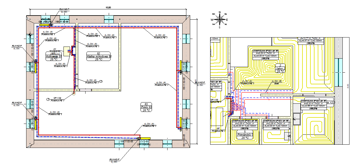
Aprēķinu rezultāti
Aprēķinu rezultāti tiek parādīti gan grafiskā, gan tabulas veidā (7. attēls). Atsevišķu sistēmas komponentu apzīmējumu formātu var brīvi mainīt (parādīto vērtību un apzīmējuma stilu atlase).
Tabulu formātu var mainīt (parādīto sleju un rindu, fontu izmēru atlase) un sakārtot pēc jebkura atslēgas kritērija.
Tabulas satur vispārējus rezultātus un detalizētus rezultātus konkrētām ierīcēm, sistēmām un materiālu un stiprinājumu sarakstus.
Rasējumos ar rezultātiem atrodami apzīmējumi, kuri satur datus par norādīto ierīci. Apzīmējumu forma ir pilnībā maināma. Visus rezultātus, kas pieejami konkrētam elementam, ir iespējams ietvert apzīmējumā. Daudzus apzīmējumu formātus var saglabāt un vēlāk uzreiz izmainīt.
Aprēķinu rezultātus ir iespējams izdrukāt ar ploteri vai printeri. Lietotājs var atlasīt rasējuma mērogu un izmantot drukas priekšskatījumu, lai noteiktu, kā rasējumi ir jāizdrukā.
Ja rasējums neietilpst vienā lapā, programma to izdrukā pa fragmentiem, kurus var salīmēt kopā. Tādējādi, pat izmantojot vienkāršāko A4 printeri, iespējams sagatavot liela izmēra rasējumus. Programma spēj arī saglabāt rasējumus kā DXF vai DWG datnes. Saglabātos rasējumus tad var ielādēt citā programmatūrā, piemēram, AutoCAD.
Tabulas ar aprēķina rezultātiem var izdrukāt vai eksportēt uz citām lietojumprogrammām, kas darbojas Windows vidē (piemēram, izklājlapās, tekstapstrādes programmā utt.).
Designing a several installations in one project
The ability to design several systems in one project in order to design the entire system for the building at the same time.

Unlimited size of the installation
Program Audytor H2O enables to design very large water supply systems (even thousands of accessories and draw-off points).

Efficient and fast calculation process
Program is equipped with a highly efficient analysis algorithm of graph installations and efficient algorithms of selection of pipes, fittings and accessories, which allow to calculate large installations in in less than a few seconds.
Creating technical documentation
Designers can use the editor of labels, creating overview of materials and components of heating systems in order to prepare technical documentation of projects. Diagrams of heating systems can be divided into any number of drawings. Drawings themselves can be exported into the DWG format.
Technical requirements
The program runs under MS Windows (10, 11) 32bit and 64 bit.
The minimum hardware:
- 1200 MHz processor,
- 4 GB RAM,
- 2 GB of free hard disk space,
- A color monitor with a minimum screen resolution of 1024x768,
- 500 MB free space on the hard drive,
- Compatible graphics card with OpenGL 2.0 and higher: all new graphics cards on the market should meet the minimum hardware requirements;
Hardware requirements for the 3D editor
Vertical resolution requirements for the screen:
- minimum - 768 points,
- sufficient for comfortable work - 900 points,
- the most convenient - 1080 points.
Requirements for system font settings:
- Windows Vista, 7, 8 - fonts "100% smaller",
- Windows XP - "normal" fonts.
The computer should have a graphics card that supports OpenGL technology in the version:
- minimum 2.0,
- sufficient for comfortable work: 3.3 and higher.
Autortiesības © v SANKOM Sp. z o.o.